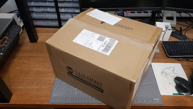
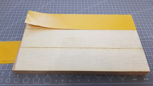
My SainSmart Genmitsu 3018 PROVer came in soon after I received the enclosure (
link to previous blog post on the enclosure). I had initially ordered a 3018 clone from one of the cheap Chinese websites, but they failed to deliver. After having a very positive experience with the SainSmart service desk regarding the enclosure (it got lost in transit, but I got a replacement shipped within 2 days; took 3 days to arrive), I decided I would reward SainSmart by buying my CNC milling machine from them as well. I ended up choosing for the PROVer version, because of it's all Aluminium frame, and emergency stop switch, offline controller, and Zero probe already in the package. I would have bought any of those seperately if they weren't included, as is often the case with the cheaper Chinese vendors.
So here's how the unboxing and assebly of my PROVer went. Pretty straight-forward, actually 😀
 |
| So here's the box |
 |
| Just like the enclosure, it is all well packaged with lots of foam, and a clear manual on top |
 |
| First layer reveals the side panels and a wiring package |
 |
| Below that, the Z-axis becomes visible already, next to the power supply and box with hardware |
 |
| So there's the entire pre-assembled X-gantry, with hte Z-axis installed already, along with the offline controller, spindle, a screwdriver, wiring spiral, and a power brick (EU style for me, which is correct) |
 |
| And let's not forget the control board, nicely encased in a plastic cage |
 |
| One more layer dow, the bed becomes visible... |
 |
| ... but it's not just the bed, it's the entire base frame assembly, so including the Y-axis |
 |
| All layed out on the desk |
 |
| The box of bits also contians the Z-probe, emergency button, clamps, some allen keys, a collet, the end-stops, and of course bolts and t-nuts to put it all together |
 |
| So there it is, layed out so that it becomes apparant what we're talking about |
 |
| So let's take out the assembly instructions. They are well written and illustrated well. And there are some things woth noticing in there. So give it a read for a change! It won't hurt; it's not much, and it can save you some trouble... |
 |
| Talking about saving some trouble... I applied thread bond to all threads from here on, plus another few that I thought would be critical. Not sure if that is necessary, but I did not want to find out when it was too late. Bertter safe than sorry, in this case! |
 |
| There's some end-stops to be screwed on, as well as some cable routing thinghies. |
 |
| Aslo for the X-axis, there's some end-stops. Don't forget the spacers at the motor end, otherwise your Z-carriage will bump into your blue coupler before it hits the end stop. This als makes the work area even smaller by some 12mm, and it's a-symmetrical. Something to be aware of when sufacing any spoilboard, should you decide to mount one. |
 |
| There's 2 rows of three t-nuts already in the base frame to mount the X-gantry. They only need to be spaced properly to accept the gantry. Luckily, they slide with quite some friction, so once positioned, they stay in place if you do nothing too radical. |
 |
| For the correct position, a spacer is added. The long tab of the spacer goes to the rear, one nut in each slot, and the third nut up against the side of the spacer. |
 |
| That should get them spaced the same sa the holes in the X-Gantry |
 |
| You can use the same spacer vertically to support the X-gantry, so that it lines the holes up with the nuts |
 |
| This was my measurement from the rear of the base frame to the rear of the X-gantry |
 |
| The other side was within 0.1mm max, which I thought was good enough for squareness over a width of some 40 cm. |
 |
| Time to assemble the spindle already! |
 |
| And that concludes the basic mechanical setup. It couldn't be much simpler |
 |
| Slot on the t-nuts only one or two turns, and orient them roughtly aligned with the profile they go into |
 |
| And that really makes it look complete |
 |
| Thanks you, SainSmart, for such an easy assebly job |
 |
| After mounting the controller, it's time for the wiring adventure |
 |
Actually, it is all very simple. All wiring is labeled, as is the control board. So it's easy to see what goes where.
The X-min and Y-max endstops both are routed through one of the chanels of the aluminium profiles. They are neatly coverd by one of those profile covers, so they are tucked away from moving parts and flying dust and chips. |
 |
| The remainder of the wiring gets bundled together with a wire spiral and some tie-wraps (also provided in abundance) |
 |
| Only the Z-probe wire and the offline controller flatcable are left out of the wire binders |
 |
| so that they can easily reach the front of the machine |
 |
| A bit more of a close-up |
 |
| measured the height of the z-probe. Mine is 13.8mm |
 |
| so that's what I added in the probe.txt file on the supplied micro-SD card. This is the Z-probing G-code you will want to add to the probing command in your G-code sending software. I will be using Candle to send my G-code, because it is supplied with the machine on the micro-SD card, it requires no installation, it's free, and it does everything I want to do with a CNC controller software. So far (a few weeks into using the machine), I have not hit any raodblocks with this software yet. Some say it is limited in it's possibilities, but I have not had a need for functionality that Candle doesn't provide. yet... 😉 |
 |
| Assembled the clamps, added the spanners for the ER-11, ... we're good to go, I would say! |
In conclusion:
This is an excellent buy! So easy to assemble. End stops were a bit fidly to get in place, but that's about all there is to it. Most of the work went into routing and tidying up the wiring. But even that was a breeze. It looks and sounds amazing, and from the first cuts with this little machine I can tell that it is nice and square as well.
I will post my experiences later, inclusing creating a spoinboard, first cuts, setting up the machine for optimum performance, cutting different materials, choice of bits, ... Stick around to see it all!
Get your 3018 PROVER here :)


Comments
Post a Comment