Calibration Time!
Time for some products to come off the board!
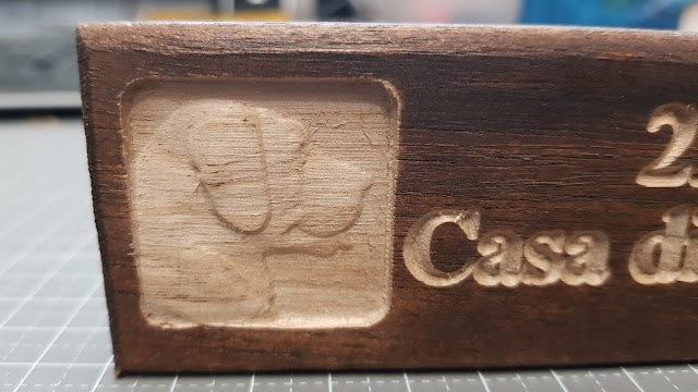
The very first product I made with my 3018 PROVer was a combination of a V-carve and a 3D carve that I had been planning ever since I started saving up for a CNC: a House Number plate with our house number on it, plus on two sides a recessed 3D carve of a Labrador
Very different from what other people use as their first product, I'm sure 😁. But I had it all prepared already, and I had some scrap wood laying around to give it a shot. So I just went for it!
Using a 60 degree V-bit for the lettering and a R0.25mm tapered ballnose bit for the 3D carving (with a 1/8" End Mill for clearing). Dimensional accuracy is not important at this stage, because I have only one part, and nothing needs to fit together yet.
For scale: the piece of wood is only 45mm high ( ~1.75", for those of you that are more comfortable with inches). So the little 3D carve is only 30x30 mm or so. Also, the wood itself is rather soft, so there were some fuzzies I had to clean out. But they let themseves be removed quite easily.
I am quite impressed with the capabilities of this machine already!
So now for some more serious milling. I have quite a few of those little scrap pieces (bout 200....), so I can experiment all I want 😁
I'll start off by pinching small holes in a piece of paper in a 100x100mm square. The distances between the corner points should all be 100mm along the sides of the square. The diagonals should measure 141mm.
As you can see, the dimensions were not very far off. To compensate for the few tenths of milimeters the sides are too long, I entered a value of 796.614 (instead of the standard 800) in the X- and Y- steps per milimeter parameter. That reduced the square to exactly 100x100mm.
To test this under load, I designed a simple square to be cut straight through the srap pieces of wood I have laying around. Just to see if the outside dimensions actually are 20mm.
And they were!
The difference may be measuring error, or the difference in flex under load when cutting along the grain as opposed to across the grain. It is small enough to take it one step further and crate also a pocket with a 20mm inside dimension, ans see if I can make the 20x20 square fit in it, both ways.
And the fit of the square into the pocket was a very sbug one in one direction, and a loose one in the other. So the actually is a small difference in dimension with or across the grain. That's probably not somethinf I can do much about, because that is determined by the response of the machine to the cutting forces. I could think of stiffening it up in the Y direction, but I think it's too soon to do that already.
Already planning some fun projects. Stick around to see more of them.
All this is done on a SainSmart Genmitsu 3018 PROVer


Comments
Post a Comment